Motion Controllers
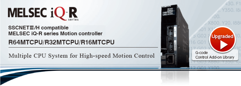
MELSEC iQ-R series
Total system performance, not individual component specifications leads to maximum performance - Based on this view, the MELSEC iQ-R series servo system controllers offer you an ideal solution to maximize your system productivity.
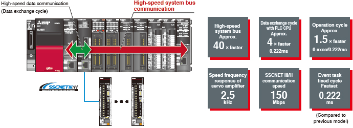
The MELSEC iQ-R series is provided with sophisticated dual engines: the PLC CPU engine for machine control and the Motion CPU engine for Motion control. The engines respectively process different types of control based on the characteristic of each engine while working together on data through a high-speed system bus. CPU loads are significantly distributed by these dual engines compared with a single engine, enabling any equipment to maximize its performance, even for a load change machine or multi-axis equipment |
The MELSERVO-J4 series servo amplifier is an environmentally and user friendly product, while offering industry-leading level of performance. Connecting the amplifiers to "SSCNETIII/H" optical network enables high-speed and high-accuracy control with the MR-J4 dedicated engine and high-resolution encoder. |
Select the most suitable combination of CPU engines that can reduce cost and maximize machine performance to the fullest from our extensive product line. Efficiency in designing and debugging is also improved.
Programming efficiency matters when it comes to productivity. The MELSEC iQ-R series optimizes all procedures, from designing, debugging, to startup. |
Equipped with advanced dual engines that are only possible with our cutting-edge iQ platform technology, the MELSEC iQ-R series takes a step further to accelerate the equipment revolution by collaborating with our partner companies. Now, a wide variety of SSCNETIII/H compatible partner products are available, such as stepping motors and direct drive motors. |
Features
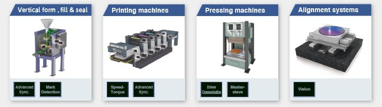
The MELSEC iQ-R series Motion controller is capable of various controls such as positioning control, speed control, torque control, tightening & press-fit control, advanced synchronous control and cam control, etc. They are applied to various machines such as X-Y tables, unwinding machines, packing machines and filling machines.
A combination of Mitsubishi's advanced PLC system, servo amplifiers, servo motors, and servo networks offers exceptional solutions that allow you to maximize your system's productivity.
Higher Basic Performance and Further Improved Total System Performance
Experience Powerful Performance of Multiple CPU with Ease of Use Just Like Using One CPU
You can select either the Motion CPU or the PLC CPU based on the application, allowing you to configure a system more flexibly.
The easy-to-understand flowchart form is adopted by Motion SFC for Motion control programming.
Also, the direct positioning start instruction allows you to program Motion control, such as positioning and synchronous controls, just with sequence programs.
Motion CPU Memory Expansion
- The cam working area has been expanded to 16M bytes, enabling you to use more cam data with higher resolution.
- The device memory has been increased to 128k words, so even multi-axis equipment requiring more devices can be applied
- The cam data storage area has been expanded to 12M bytes. SD card is also available for storing cam data.
Ease of Use Achieved by a State-of-art CPU Buffer MemoryRevolutionary
The high-speed, high-capacity CPU buffer memory revolutionizes the data exchange between CPUs.
The PLC CPU and the Motion CPU each have a CPU buffer memory. And those buffer memories are efficiently utilized for two different purposes.
- The 2M words CPU buffer memory (Motion CPU side) is provided as standard, which is utilized for bulky data transmission and fast data updating.
- The CPU buffer memory (fixed-cycle communication area) allows 24 k words (4 CPUs in total) transmission between the PLC CPU and the Motion CPU every 0.222 ms. It is perfectly suited for receiving/transmitting highly synchronized data between multiple CPUs.
CPU Buffer MemoryProductivityEngineering
The Motion CPU and the PLC CPU are equipped with 2 M words and 512 k words CPU buffer memories respectively.
They allow for bulky data transmission and fast data update.
Example of using PLC CPU buffer memory
Bulky data such as cam data can be transferred by just a one-time transmission through the 512 k word buffer memory.
Example of using Motion CPU buffer memory
The data that is set on Motion CPU side can be reflected to the interlock in the sequence program without any delay.
CPU Buffer Memory (Fixed-cycle Communication Area)
Data can be transmitted every 0.222 ms between the PLC CPU and the Motion CPU. The CPU buffer memories (fixed-cycle communication area) are synchronized to the Motion control, optimizing the operation.
Motion SFC Program
The Motion control
program is described in flowchart form using the Motion SFC (Sequential
Function Chart) format.
The Motion SFC format program is suitable for event processing and allows the
Motion CPU to perform batch control of multiple sequential machine operations,
pursuing high event responsiveness.
Flowchart description is easy to
read and understand
·
The machine operation
procedure is visualized in the program by using the flowchart descriptions.
· A process control program can be created easily, and control details can be visualized.
Controlling sequential machine operation using
the Motion CPU
·
Servo control, I/O
control, and operation commands can be combined in the Motion SFC program.
· Motion SFC program can execute servo control by itself, eliminating the need of creating the sequence program for servo control.
High-speed Synchronous Network SSCNETIII/H
§ Communications speed is increased to 150 Mbps full duplex (equivalent to 300 Mbps half duplex), three times faster than the conventional speed.
System response is dramatically improved.
§ Smooth control of a machine is possible using
high-speed serial communications with a cycle time of 0.222 ms.
§ Synchronous communications are achieved with
SSCNETIII/H, offering technical advantages for machines that require
deterministic control.
§ Long distance wiring is possible up to 3200 m
(10498.69 ft.) per system (maximum of 100 m (328.08 ft.) between stations x
control axes up to 32 axes), suitable for large-scale systems.
§ SSCNETIII/H compatible and SSCNETIII compatible
servo amplifiers can be used together.
(The communications speed when SSCNETIII compatible products are used together
in the same system: 150 Mbps full duplex)
(Note): SSCNET (Servo System Controller Network)
Positioning Control
A variety of positioning controls, such as PTP control, position follow-up, and continuous trajectory control are available with the Motion controller.
Basic Positioning Control
· To respond to various
applications, the Motion controller offers various control methods such as PTP
control, speed control, speed-position switching control, continuous trajectory
control, position follow-up control, Speed control with fixed position stop,
and high-speed oscillation control, etc.
·
Powerful auxiliary
functions are available such as M-codes, the target position change function,
the acceleration/deceleration time change function, and the advanced S-curve
acceleration/deceleration.
· Positioning operation can be activated by Motion SFC, or the direct positioning start instruction by the PLC CPU, etc.
Advanced Synchronous Control
The advanced
synchronous control can be achieved using software instead of controlling
mechanically with physical gears, shafts, clutches, speed change gears or cams
etc. Additionally, a cam is easily created with the cam auto-generation
function.The synchronous control can be started/ended on axis-by-axis
basis.Axes in synchronous and positioning controls can be used together in one
program.
Speed-torque control can be performed simultaneously with the synchronous
control.
All axes are synchronized using a synchronous
encoder axis or a servo input axis.
Application Packing machines, printing
machines, diaper
manufacturing machines, tire molder, etc.
Only two axes are in synchronization. Axis 2
is set as to synchronize to axis 1. The other axes are in positioning control.
Application Tandem configuration, etc.
Multiple CPU advanced synchronous control
A large system can be configured thanks to the advanced synchronous control that allows up to 192-axis synchronization with high accuracy by use of three Motion CPU modules.
Synchronous Control Parameters
· The synchronous
control is easily executed just by setting parameters.
· One of the following
three can be set as the input axis: Synchronous encoder axis, Command
generation axis, or Servo input axis.
· "Command
generation axis" is not counted as a control axis; therefore all the
control axes can be used as output axes.
· The cam axis can be operated in linear operation (a rotary table, a ball screw, etc.), two-way operation, or feed operation by setting cam No. and cam data.
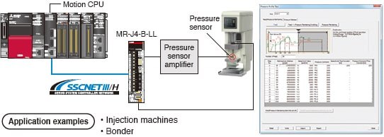
Pressure Control
The machine is controlled so that the pressure commands match the pressure sensor values; therefore pressure is maintained constant even with a changing load. Each pressure process ("Feed", "Pressure maintaining", and "Pressure release") can be set with the Pressure Profile, and those processes can be tested on MELSOFT MT Works2, which makes a changeover and adjustment easy.
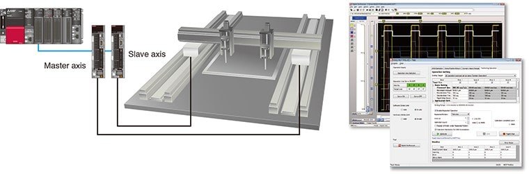
Multi-axis Adjustment Function
The multi-axis adjustment function enables
simpler servo adjustment and quicker startup for machines executing multi-axis
simultaneous operation, such as a tandem configuration.
·
Multi-axis
simultaneous JOG operation by specifying speed and acceleration/deceleration
time
·
Multi-axis
simultaneous positioning
· Multi-axis simultaneous tuning by the same settings
Machine Control Function
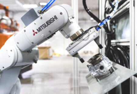
This Motion controller
controls the simple industrial robot by installing the machine library.
The control method of the robots is a machine control which controls in a three
dimensional (XYZ) Cartesian coordinates space.
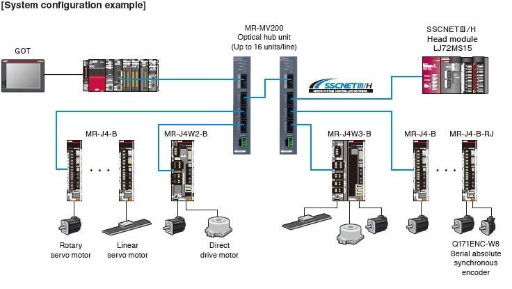
Optical Hub Unit
The MR-MV200 optical hub unit can branch a
single SSCNETIII/H network line in three separate directions. This enables
distribution of the SSCNETIII/H compatible devices with flexible wiring
arrangement. In addition, the distributed amplifier can be partly OFF for
maintenance without stopping the whole system; thus, the machine availability
can be improved.
·
The SSCNET
connect/disconnect function of the controller allows you to power off only the
desired servo amplifiers.
·
The optical hub unit
is introduced just by making some changes in wiring without making any new
settings.
·
Longer-distance wiring
becomes available by using the optical hub unit.
(Note): Be sure to confirm that "SSCNETIII/H"
is selected in the system setting when introducing the optical hub unit.
Motion Controller
The MELSEC iQ-R series Motion controller aims to make any equipment faster and more accurate, allowing you to configure a one-of-a-kind, specialized machine system.
Simple Motion module
The MELSEC iQ-R series Simple Motion module allows you to upgrade your machine with less effort.
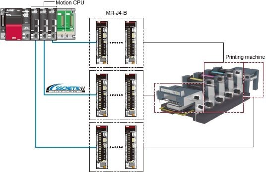
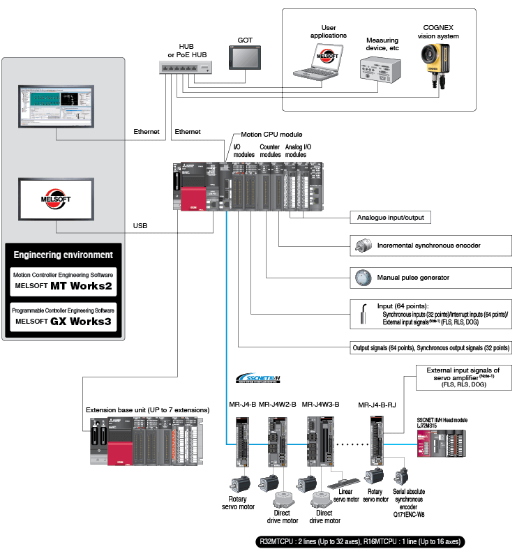
The R16MTCPU, R32MTCPU and R64MTCPU Motion CPUs for the iQ-R Platform provide industry-leading performance for the most demanding motion applications for the Food and Beverage, Packaging, Automotive, and Printing industries. These motion CPUs use standard I/O modules for incremental encoders and high speed inputs, so no special hardware options are required. Serial absolute synchronous encoders are connected through the MR-J4-B-RJ servo drive.
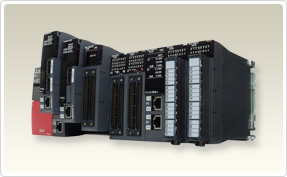
System Configuration
Motion CPU R64MTCPU/R32MTCPU/R16MTCPU Module Specifications
Notes:
1. Servo amplifiers
for SSCNET cannot be used.
2. SSCNETIII and
SSCNETIII/H cannot be combined within the same line. For R64MTCPU/R32MTCPU,
SSCNETIII and SSCNETIII/H can be set for each line.
3. For half-duplex transmission, response time may be longer depending on the external device. When connecting with an external device via a switching HUB, set to full-duplex transmission.
Motion CPU R64MTCPU/R32MTCPU/R16MTCPU Module Specifications (continued)
|
Model Number |
R64MTCPU |
R32MTCPU |
R16MTCPU |
||
|
Stocked Item |
S |
S |
S |
||
|
Number of Control Axes |
Up to 64 axes |
Up to 32 axes |
Up to 16 axes |
||
|
SSCNET Communication (*1) |
Communication Type |
SSCNETIII/H,
SSCNETIII |
|||
|
Number of Lines |
2 lines (*2) |
1 line (*2) |
|||
|
Distance Between Stations
(Maximum) m (ft) |
SSCNETIII/H |
100 (328.08) |
|||
|
SSCNETIII |
50 (164.04) |
||||
|
Combined Cable Length (Maximum) m
(ft) |
SSCNETIII/H |
1600 (5249.30) |
|||
|
SSCNETIII |
800 (2624.70) |
||||
|
Number of SSCNETIII/H Head Module
Connection Stations |
Up to 8 stations
(Up to 4 stations/line) |
Up to 4 stations |
|||
|
Number of Optical Hub Unit
Connections |
Up to 32 units
(Up to 16 units/line) |
Up to 16 units |
|||
|
PERIPHERAL I/F (Ethernet) |
Data Transmission Speed |
100Mbps/10Mbps |
|||
|
Communication Mode |
Full-duplex/Half-duplex
(*3) |
||||
|
Transmission Method |
Base band |
||||
|
Cable Length (Maximum) m (ft) |
30 (98.43) |
||||
|
Memory Card Slot |
SD/SDHC memory
card compatible |
||||
|
Memory Capacity |
Standard ROM |
12MB |
|||
|
SD Memory Card |
Memory card
capacity (Up to 32B) |
||||
|
Number of Stages of Extension Base |
Up to 7 stages |
||||
|
Internal Current Consumption 5VDC
(A) |
1.20 |
||||
|
Weight (kg) |
0.28 |
||||
|
Dimensions mm (inch) (H x W x D) |
106.0 x 27.8 x
110.0 (4.17 x 1.09 x 4.33) |
||||
Notes:
1. Servo amplifier
(MR-J4-_B-LL) only.
2. Servo amplifier
(MR-J4-_B-RJ) only.
3. Servo amplifier
(MR-J3-_B/MR-J4-_B) only.
|
Model Number |
R64MTCPU |
R32MTCPU |
R16MTCPU |
|
|
Operation Cycle (Default) |
0.222ms/ 1 to 2
axes |
0.222ms/ 1 to 2
axes |
0.222ms/ 1 to 2
axes |
|
|
Interpolation Functions |
Linear
interpolation (Up to 4 axes), Circular interpolation (2 axes), Helical
interpolation (3 axes) |
|||
|
Control Modes |
PTP (Point to
Point) control, Speed control, Speed-position switching control, Fixed-pitch
feed, Continuous trajectory control, Position follow-up control, Speed
control with fixed position stop, High-speed oscillation control,
Speed-torque control, Pressure control (*1), Advanced synchronous control,
Machine control |
|||
|
Acceleration/Deceleration Control |
Trapezoidal
acceleration/deceleration, S-curve acceleration/deceleration, Advanced
S-curve acceleration/deceleration |
|||
|
Compensation |
Backlash
compensation, Electronic gear, Phase compensation |
|||
|
Programming Language |
Motion SFC,
Dedicated instruction |
|||
|
Servo Program Capacity |
32k steps |
|||
|
Number of Positioning Points |
6400 points
(Positioning data can be designated indirectly) |
|||
|
Peripheral I/F |
PERIPHERAL I/F |
|||
|
Home Position Return Function |
Proximity dog
method (2 types), Count method (3 types), Data set method (2 types), Dog
cradle method, Stopper method (2 types), Limit switch combined method, Scale
home position signal detection method, Dogless home position signal reference
method, Driver home position return method. Home position return re-try
function provided, home position shift function provided |
|||
|
JOG Operation Function |
Provided |
|||
|
Manual Pulse Generator Operation
Function |
Possible to
connect 3 modules (High-speed counter module use) |
|||
|
Synchronous Encoder Operation
Function |
Possible to
connect 12 modules (Via module (High-speed counter module use) + Via servo
amplifier (*2) + Via device + Multiple CPU advanced synchronous control) |
|||
|
M-Code Function |
M-code output
function provided, M-code completion wait function provided |
|||
|
Limit Switch Output Function |
Number of output
points 64 points x 2 settings Output timing compensation. Watch data: Motion
control data/Word device |
|||
|
ROM Operation Function |
Provided |
|||
|
Multiple CPU Advanced Synchronous
Control |
Provided |
|||
|
External Input Signal |
External input
signals (FLS/RLS/DOG) of servo amplifier, Bit device |
|||
|
Forced Stop |
Motion controller
forced stop (Device), Forced stop terminal of servo amplifier |
|||
|
Number of I/O Points |
Total 4096 points |
|||
|
Mark Detection Function |
Mark Detection Mode Setting |
Continuous
detection mode, Specified number of detection mode, Ring buffer mode |
||
|
Mark Detection Signal |
High-speed input
request signal (bit device, input signal of servo amplifier (DI1 to DI3) |
|||
|
Mark Detection Setting |
64 settings |
|||
|
Clock Function |
Provided |
|||
|
Security Function |
Provided |
|||
|
All Clear Function |
Provided |
|||
|
Remote Operation |
Remote RUN/STOP |
|||
|
File Management Function |
Available for
program and parameter data, cam data, label data, sampling data etc. |
|||
|
Optional Data Monitor Function |
SSCNETIII/H |
Up to 14
data/axis (Communication data: Up to 6 points/axis) |
||
|
SSCNETIII |
Up to 14
data/axis (Communication data: Up to 3 points/axis) |
|||
|
Digital Oscilloscope Function |
Motion buffering
method (Real-time waveform can be displayed). Sampling data: Word 16CH, Bit
16CH. Offline sampling |
|||
|
Absolute Position System |
Compatible by
setting battery to servo amplifier. (Possible to select the absolute data
method or incremental method for each axis) |
|||
|
Driver Communication Function (*3) |
Provided |
|||
|
File Transmission at Boot Function |
Provided |
|||
|
Parameter Change Function |
Provided |
|||
|
Event History Function |
Provided |
|||
|
Add-on Function |
Provided |
|||
|
Override Function |
Provided |
|||
|
Vibration Suppression Command
Filter |
Provided |
|||