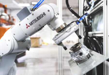
Industrial Robot
MELFA FR SERIES
Evolved intelligence realizes advances in work procedures, cooperation between people and robots, and e-F@ctory-compatibility, making next-generation manufacturing a reality.
With globalization and increasingly diverse consumer needs in the market, the manufacturing industries face a time of considerable change.
It is no longer enough for industrial robots to simply perform a single task. Industry now demands robots with the capacity and flexibility to readily take on more sophisticated tasks.
The MELFA FR series provides new, more intelligent solutions that underpin "next-generation manufacturing", offering a simpler approach to advanced and flexible production. These robots can handle all your automation needs.
| MELFA FR series |
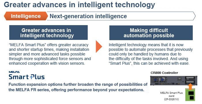
"Next-generation intelligent functions" make it simple to carry out work that has always defied automation.
"Safe, collaborative work applications" allow robots and people to work together with high levels of safety.
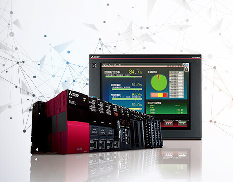
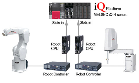
"FA-IT integration functions" support next generation manufacturing.
With these 3 key features, the FR Series is capable of handling virtually all your automation needs.

 Intelligence Technology Intelligence Technology |
| FA-IT Integration |

| Safety |

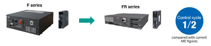
| Improved controller performance |
Control cycles on FR series controllers take just half the current time, improving robot control performance.
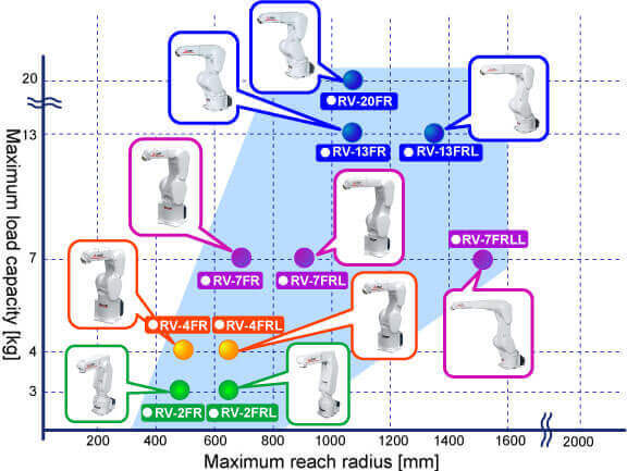
| MELFA FR series (Vertical Type) |
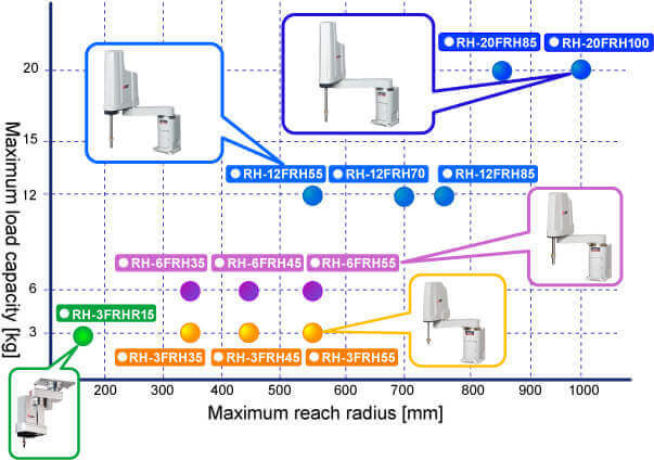
| MELFA FR series (Horizontal Type) |
|
Model Number |
RV2FR |
RV2FRL |
RV4FR |
RV4FRL |
RV7FR |
RV7FRL |
RV7FRLL |
RV13FR |
RV13FRL |
RV20FR |
|
|
Maximum Load Capacity (kg) |
2 |
2 |
4 |
4 |
7 |
7 |
7 |
13 |
13 |
20 |
|
|
Maximum Reach Radius (mm) |
504 |
649 |
515 |
649 |
713 |
908 |
1,503 |
1,094 |
1,388 |
1,094 |
|
|
Environmental Specifications |
Standard |
IP30 |
IP40 |
||||||||
|
Oil Mist |
– |
IP67 |
|||||||||
|
Cleanroom |
– |
ISO class3 |
|||||||||
|
Controller |
CR800-R, CR800-D |
||||||||||
Through Wrist
Wiring/Piping Options (RVFR Series)
Tooling Device
Configuration (4kg – 20kg)
|
Hand Configuration |
Wiring Format |
Robot Specifications |
Required Device |
Remarks |
|
|
External Wiring Set for the
Forearm |
External Wiring Set for the Base |
||||
|
Air-Hand + Hand Input Signal |
Interior
equipment |
SHxx01 |
- (*1) |
- |
Air hoses: Up to
2 systems |
|
Exterior
equipment |
Standard |
- (*2) |
- |
Air hoses: Up to
4 systems |
|
|
Hand Input Signal + Ethernet +
Force Sensor OR Electric Hand (*3, *4) |
Interior
equipment |
-SHxx02 |
- (*1) |
1F-HA01S-01
(Included) |
|
|
Exterior
equipment |
Standard |
1F-HB01S-01 |
1F-HA01S-01 |
Air hoses: Up to 4
systems |
|
|
Electric Hand + Ethernet |
Interior
equipment |
-SHxx03 |
- (*1) |
1F-HA02S-01
(Included) |
|
|
Exterior
equipment |
Standard |
1F-HB02S-01 |
1F-HA02S-01 |
||
|
Air-Hand + Hand Input Signal +
Force Sensor |
Interior equipment |
-SHxx04 |
- (*1) |
1F-HA01S-01
(Included) |
Air hoses: Up to
1 system |
|
Exterior
equipment |
Standard |
1F-HB01S-01 |
1F-HA01S-01 |
Air hoses: Up to
4 systems |
|
|
Air-Hand + Hand Input Signal +
Ethernet |
Interior
equipment |
-SHxx05 |
- (*1) |
1F-HA01S-01
(Included) |
Air hoses: Up to
1 system |
|
Exterior
equipment |
Standard |
1F-HB01S-01 |
1F-HA01S-01 |
Air hoses: Up to
4 systems |
|
Notes:
1. For internal
routing. (Pneumatics sold separately)
2. For external
routing. (Hoses, input cables and solenoid valves sold separately)
3. For SHxx02
configuration, the Air hand and Electric hand cannot be used simultaneously.
4. For SHxx02
configuration, the Force sensor and Electric hand cannot be used
simultaneously.
RVFR Series Part
Number Configuration
RV2FR • RV2FRL
|
Model Number |
RV2FR(B) |
RV2FRL(B) |
|
|
Environmental Specifications |
Standard |
||
|
Protection Degree |
IP30 |
||
|
Installation |
Floor type, ceiling type,
(wall-mounted type) (*2) |
||
|
Structure |
Vertical, multiple-joint type |
||
|
Degrees of Freedom |
6 |
||
|
Drive System (*1) |
AC servo motor (J2, J3 and J5:
with brake) |
||
|
Position Detection Method |
Absolute encoder |
||
|
Maximum Load Capacity (Rating) kg |
Maximum 3 (Rated 2) (*5) |
||
|
Arm Length (mm) |
230 + 270 |
310 + 335 |
|
|
Maximum Reach Radius (mm) |
504 |
649 |
|
|
Operating Range (deg) |
J1 |
480 (±240) |
|
|
J2 |
240 (±120) |
237 (-117 to +120) |
|
|
J3 |
160 (-0 to +160) |
||
|
J4 |
400 (±200) |
||
|
J5 |
240 (±120) |
||
|
J6 |
720 (±360) |
||
|
Maximum Speed (deg/sec) |
J1 |
300 |
225 |
|
J2 |
150 |
105 |
|
|
J3 |
300 |
165 |
|
|
J4 |
450 |
412 |
|
|
J5 |
450 |
||
|
J6 |
720 |
||
|
Maximum Composite Speed (mm/sec)
(*3) |
4955 |
4200 |
|
|
Cycle Time (sec) (*4) |
0.6 |
0.7 |
|
|
Position Repeatability (mm) |
±0.02 |
||
|
Ambient Temperature (°C) |
0 to 40 |
||
|
Weight (kg) |
19 |
21 |
|
|
Tolerable Moment (Nm) |
J4 |
4.17 |
|
|
J5 |
4.17 |
||
|
J6 |
2.45 |
||
|
Tolerable Amount of Inertia (kgm²) |
J4 |
0.18 |
|
|
J5 |
0.18 |
||
|
J6 |
0.04 |
||
|
Tool Wiring |
Gripper: 4 input points/4 output
points; Signal cable for the multi-function gripper |
||
|
Tool Pneumatic Pipes |
ø4 x 4 (Base to forearm section) |
||
|
Machine Cable |
5m (connector on both ends) |
||
|
Connected Controller |
CR800-D (iQ-R
functionality supported via optional 4F-R16RTCPU and software setting change) |
||
Notes:
1. The standard model
does not have a brake on the J1, J4, or J6 axis. There are models available
with brakes included for all axes.
2. The wall-mounted
specification is a custom specification where the operating range of the
J1-axis is limited.
3. This is the value
at the surface of the mechanical interface when all axes are composited.
4. The cycle time is
based on back-and-forth movement over a vertical distance of 25 mm and
horizontal distance of 300 mm when the load is 1 kg.
5. The maximum load
capacity indicates the maximum payload when the mechanical interface is facing
downward (±10° to the perpendicular).
RV4FR • RV4FRL
|
Model Number |
RV4FRM/C |
RV4FRLM/C |
|
|
Environmental Specifications |
Standard / Oil Mist / Cleanroom |
||
|
Protection Degree |
IP40 (standard) / IP67 (oil mist)
(*1) / ISOclass3 (*6) |
||
|
Installation |
Floor type, ceiling type,
(wall-mounted type) (*2) |
||
|
Structure |
Vertical, multiple-joint type |
||
|
Degrees of Freedom |
6 (*8) |
||
|
Drive System (*1) |
AC servo motor |
||
|
Position Detection Method |
Absolute encoder |
||
|
Maximum Load Capacity (Rating) kg |
Maximum 4 (Rated 4) (*7) |
||
|
Arm Length (mm) |
235+275 |
310+335 |
|
|
Maximum Reach Radius (mm) |
515 |
649 |
|
|
Operating Range (deg) |
J1 |
480 (±240) |
|
|
J2 |
240 (±120) |
||
|
J3 |
161 (-0 to +161) |
164 (-0 to +164) |
|
|
J4 |
400 (±200) |
||
|
J5 |
240 (±120) |
||
|
J6 |
720 (±360) |
||
|
Maximum Speed (deg/sec) |
J1 |
450 |
420 |
|
J2 |
450 |
336 |
|
|
J3 |
300 |
250 |
|
|
J4 |
540 |
540 |
|
|
J5 |
623 |
623 |
|
|
J6 |
720 |
720 |
|
|
Maximum Composite Speed (mm/sec)
(*3) |
9027 |
9048 |
|
|
Cycle Time (sec) (*4) |
0.36 |
0.36 |
|
|
Position Repeatability (mm) |
±0.02 |
||
|
Ambient Temperature (°C) |
0 to 40 |
||
|
Weight (kg) |
39 |
41 |
|
|
Tolerable Moment (Nm) |
J4 |
6.66 |
|
|
J5 |
6.66 |
||
|
J6 |
3.96 |
||
|
Tolerable Amount of Inertia (kgm²) |
J4 |
0.2 |
|
|
J5 |
0.2 |
||
|
J6 |
0.1 |
||
|
Tool Wiring |
Gripper: 8 input points/8 output
points; Signal cable for the multi-function gripper and sensors; LAN × 1
<100 BASE-TX> (*5) |
||
|
Tool Pneumatic Pipes |
Primary: ø6 × 2 Secondary: ø4 × 8,
ø4 × 4 (from base portion to forearm) |
||
|
Machine Cable |
5m (connector on both ends) |
||
|
Connected Controller |
CR800-D (iQ-R functionality
supported via optional 4F-R16RTCPU and software setting change) |
||
Notes:
1. Please contact a
Mitsubishi Electric dealer since the environmental resistance may not be
secured depending on the characteristics of oil you use. Air will need to be
purged from the lines. For details, refer to the specifications sheet.
2. The wall-mounted
specification is a custom specification where the operating range of the
J1-axis is limited.
3. This is the value
at the surface of the mechanical interface when all axes are composited.
4. The cycle time is
based on back-and-forth movement over a vertical distance of 25 mm and
horizontal distance of 300 mm when the load is 1 kg.
5. Can also be used as
a spare line (0.13 sq. mm, 4-pair cable) for conventional models.
6. Preservation of
cleanliness levels depends on conditions of a downstream flow of 0.3 m/s in the
cleanroom and internal robot suctioning. A ø8-mm coupler for suctioning is
provided at the back of the base.
7. The maximum load
capacity indicates the maximum payload when the mechanical interface is facing
downward (±10° to the perpendicular).
8. Please contact our
sales offices if you need a five axes long arm model.
RV7FR • RV7FRL •
RV7FRLL
|
Model Number |
RV7FRM/C |
RV7FRLM/C |
RV7FRLLM/C |
|
|
Environmental Specifications |
Standard / Oil Mist / Cleanroom |
|||
|
Protection Degree |
IP40 (standard) / IP67 (oil mist)
(*1) / ISO class3 (*6) |
|||
|
Installation |
Floor type, ceiling type,
(wall-mounted type) (*2) |
|||
|
Structure |
Vertical, multiple-joint type |
|||
|
Degrees of Freedom |
6 |
|||
|
Drive System (*1) |
AC servo motor |
|||
|
Position Detection Method |
Absolute encoder |
|||
|
Maximum Load Capacity (Rating) kg |
Maximum 7 (Rated 7) (*7) |
|||
|
Arm Length (NO1 am) |
340 + 370 |
435+470 |
565+805 |
|
|
Maximum Reach Radius (mm) |
713 |
908 |
1503 |
|
|
Operating Range (deg) |
J1 |
480 (±240) |
380 (±190) |
|
|
J2 |
240 (-115 to +125) |
240 (-110 to +130) |
240 (-90 to +150) |
|
|
J3 |
156 (-0 to +156) |
162 (-0 to +162) |
167.5 (-10 to +157.5) |
|
|
J4 |
400 (±200) |
|||
|
J5 |
240 (±120) |
|||
|
J6 |
720 (±360) |
|||
|
Maximum Speed (deg/sec) |
J1 |
360 |
288 |
234 |
|
J2 |
401 |
321 |
164 |
|
|
J3 |
450 |
360 |
219 |
|
|
J4 |
337 |
337 |
375 |
|
|
J5 |
450 |
450 |
450 |
|
|
J6 |
720 |
720 |
720 |
|
|
Maximum Composite Speed (mm/sec)
(*3) |
11064 |
10977 |
15,300 |
|
|
Cycle Time (sec) (*4) |
0.32 |
0.35 |
0.63 |
|
|
Position Repeatability (mm) |
±0.02 |
±0.06 |
||
|
Ambient Temperature (°C) |
0 to 40 |
|||
|
Weight (kg) |
65 |
67 |
130 |
|
|
Tolerable Moment (Nm) |
J4 |
16.2 |
||
|
J5 |
16.2 |
|||
|
J6 |
6.86 |
|||
|
Tolerable Amount of Inertia (kgm²) |
J4 |
0.45 |
||
|
J5 |
0.45 |
|||
|
J6 |
0.10 |
|||
|
Tool Wiring |
Gripper: 8 input points, Signal
cable for the multi-function gripper, LAN × 1 <100 BASE-TX> (*5) |
|||
|
Tool Pneumatic Pipes |
Primary: ø6 × 2 Secondary: ø4 × 8,
ø4 × 4 (from base portion to forearm) |
Primary: ø6 × 2 Secondary: ø6 × 8,
ø4 × 4 (from base portion to forearm) |
||
|
Machine Cable |
5m (connector on both ends) |
|||
|
Connected Controller |
CR800-D (iQ-R functionality
supported via optional 4F-R16RTCPU and software setting change) |
|||
Notes:
1. Please contact
Mitsubishi Electric dealer since the environmental resistance may not be
secured depending on the characteristics of oil you use.
2. The wall-mounted
specification is a custom specification where the operating range of the
J1-axis is limited.
3. This is the value
at the surface of the mechanical interface when all axes are composited.
4. The cycle time is
based on back-and-forth movement over a vertical distance of 25 mm and
horizontal distance of 300 mm when the load is 1 kg.
5. Can also be used as
a spare line (0.13 sq. mm, 4-pair cable) for conventional models.
6. Preservation of cleanliness
levels depends on conditions of a downstream flow of 0.3 m/s in the cleanroom
and internal robot suctioning. A ø8-mm coupler for suctioning is provided at
the back of the base.
7. The maximum load
capacity indicates the maximum payload when the mechanical interface is facing
downward (±10° to the perpendicular).
RV13FR • RV13FRL
|
Model Number |
RV13FRM/C |
RV13FRLM/C |
RV20FRM/C |
|
|
Environment |
Standard / Oil Mist / Cleanroom |
|||
|
Protection Degree |
IP40 (standard), IP67 (oil mist)
(*1), ISO Class 3 (*6) |
|||
|
Mounting Position |
Floor type, ceiling type,
(wall-mounted type) (*2) |
|||
|
Structure |
Vertical, multiple-joint type |
|||
|
Degree of Freedom |
6 axis |
|||
|
Drive System |
AC servo motor |
|||
|
Position Detection Method |
Absolute encoder |
|||
|
Maximum Payload (Rated) kg |
Maximum 13 (Rated 12) (*7) |
Maximum 20 (Rated 15) |
||
|
Arm Length (mm) |
410 + 550 |
565 + 690 |
410 + 550 |
|
|
Maximum Reach Radius (mm) |
1,094 |
1,388 |
1,094 |
|
|
Operating Range (deg) |
J1 |
380 (±190) |
||
|
J2 |
240 (-90 to +150) |
|||
|
J3 |
167.5 (-10 to +157.5) |
|||
|
J4 |
400 (±200) |
|||
|
J5 |
240 (±120) |
|||
|
J6 |
720 (±360) |
|||
|
Maximum Speed (deg/sec) |
J1 |
290 |
234 |
110 |
|
J2 |
234 |
164 |
110 |
|
|
J3 |
312 |
219 |
110 |
|
|
J4 |
375 |
375 |
124 |
|
|
J5 |
375 |
375 |
125 |
|
|
J6 |
720 |
720 |
360 |
|
|
Synthetic Maximum Speed (mm/sec)
(*3) |
10,450 |
9,700 |
4200 |
|
|
Cycle Time (sec) (*4) |
0.53 |
0.68 |
0.70 |
|
|
Position Repeatability (mm) |
±0.05 |
|||
|
Ambient Temperature (°C) |
0 to 40 |
|||
|
Weight (kg) |
120 |
130 |
120 |
|
|
Allowable Movement (Nm) |
J4 |
19.3 |
49.0 |
|
|
J5 |
19.3 |
49.0 |
||
|
J6 |
11 |
11 |
||
|
Allowable Inertia (KGM2) |
J4 |
0.47 |
1.40 |
|
|
J5 |
0.47 |
1.40 |
||
|
J6 |
0.14 |
0.14 |
||
|
Tool Wiring |
Gripper: 8 input points/8 output
points; Signal cable for the multi-function gripper; LAN × 1 <100
BASE-TX> (*5) |
|||
|
Tool Pneumatic Pipes |
Primary: ø6 × 2 Secondary: ø6 × 8,
ø4 × 4 (from base portion to forearm) |
|||
|
Machine Cable |
5m (connector on both ends) |
|||
|
Connection Controller |
CR800-D (iQ-R functionality
supported via optional 4F-R16RTCPU and software setting change) |
|||
Notes:
1. Please contact
Mitsubishi Electric dealer since the environmental resistance may not be
secured depending on the characteristics of oil you use.
2. The wall-mounted specification
is a custom specification where the operating range of the J1-axis is limited.
3. This is the value
at the surface of the mechanical interface when all axes are composited.
4. The cycle time is
based on back-and-forth movement over a vertical distance of 25 mm and
horizontal distance of 300 mm when the load is 5 kg.
5. Can also be used as
a spare line (0.13 sq. mm, 4-pair cable) for conventional models. Provided up
to the inside of the forearm.
6. Preservation of
cleanliness levels depends on conditions of a downstream flow of 0.3 m/s in the
cleanroom and internal robot suctioning. A 8-mm coupler for suctioning is
provided at the back of the base.
7. The maximum load
capacity indicates the maximum payload when the mechanical interface is facing downward
(±10° to the perpendicular).