
Network-related products |
Programmable Controllers MELSEC
CC-Link IE TSN Specifications

- Feature
- Specification
- Standards
- Discontinued
Specifications
General specifications
The following table provides the environmental specifications required for using the CC-Link IE TSN master/local module and block-type modules listed in this catalog. For the environmental specifications required to use other products, please refer to the relevant product catalog or manual.
| Item | MELSEC iQ-R Series master/local module Block-type remote module |
MELSEC iQ-F Series master/local module |
|---|---|---|
| Operating ambient temperature (°C) | 0…55 *1 | -20…55, non-freezing *2*3 |
| Storage ambient temperature (°C) | -25…75 | |
| Operating ambient humidity (% RH) | 5…95, non-condensing | |
| Storage ambient humidity (% RH) | ||
| Vibration resistance | Please refer to the relevant product manual | |
| Shock resistance | Compliant with JIS B 3502 and IEC 61131-2 (147 m/s 2, 3 times each in directions X, Y, and Z) |
147 m/s 2, Action time: 11 ms, 3 times each in directions X, Y, and Z by half-sine pulse *4 |
| Operating atmosphere | No corrosive gases *5, no flammable gases, no excessive conductive dust | |
| Operating altitude *6 (m) | 0…2000 *7 | |
| Installation location | Inside a control panel | |
| Overvoltage category *8 | ≤Ⅱ | |
| Pollution level *9 | ≤ 2 | |
- *1.Enables standard MELSEC iQ-R Series modules to support extended operating ambient temperature of 0 to 60°C, ensuring the same performance as the standard operating ambient temperature (0 to 55°C). When requiring to use in an ambient temperature environment higher than 60°C, please consult your local Mitsubishi Electric representative.
- *2.In the case where operating ambient temperature is lower than 0°C, the specifications are different from the above description. For details, please refer to the “MELSEC iQ-F FX5U User's Manual (Hardware)”.
- *3.When using FX5-CCLGN-MS manufactured in December 2020 or earlier, the operating ambient temperature is -20 to 50°C. The operating ambient temperature of the programmable controller system is the same.
- *4.The criterion is shown in IEC 61131-2.
- *5.For RJ71GN11-T2 and RJ71GN11-EIP, the special coated products, which improve resistance to corrosive gas concentrations as specified in IEC 60721-3-3: 1994 3C2, are available for the use in a corrosive gas environment. For details of the special coated products, please consult your local Mitsubishi Electric representative.
- *6.Do not use or store the programmable controller under pressure higher than the atmospheric pressure of altitude 0 m. Doing so may cause malfunction or lead to failure.
- *7.When using programmable controllers at an altitude higher than 2000 m, the upper limits of the permissible voltage and the operating ambient temperature become lower. For further details, please refer to the technical bulletin “FA-A-0152” for the MELSEC iQ-R Series and “HIME-T-P-0185” for the MELSEC iQ-F Series.
- *8.This indicates the section of the power supply to which the equipment is assumed to be connected between the public electrical power distribution network and the machinery within premises. Category II applies to equipment for which electrical power is supplied from fixed facilities. The surge voltage withstand level for up to the rated voltage of 300 V is 2500 V.
- *9.This index indicates the degree to which conductive material is generated in terms of the environment in which the equipment is used. Pollution level 2 is when only non-conductive pollution occurs. Temporary conductivity caused by condensation must be expected occasionally.
Performance specifications
| Item | MELSEC iQ-R Series master/local module RJ71GN11-T2 |
MELSEC iQ-R Series CC-Link IE TSN Plus master/local module RJ71GN11-EIP |
|
|---|---|---|---|
| Communication speed (bps) | 1G/100M | 1G/100M | |
| Maximum stations per network *11 | 121 | 121 | |
| Connection cable | Ethernet cable (Category 5e or higher) |
Ethernet cable (Category 5e or higher) |
|
| Overall cable distance (m) | Line: 12000 Ring: 12100 Others: Depends on the system configuration |
Line: 12000 Others: Depends on the system configuration |
|
| Maximum station-to-station distance (m) | 100 | 100 | |
| Max. number of networks | 239 | 239 | |
| Network topology *12 | Line, star *13, ring | Line *14, star *13 | |
| Communication method | Time-sharing method/time-managed polling method | Time-sharing method | |
| Maximum link points per network | |||
| RX/RY | 16384 points, 2 kbytes | 16384 points, 2 kbytes | |
| RWr/RWw | 8192 points, 16 kbytes | 8192 points, 16 kbytes | |
| LB | 32768 points, 4 kbytes | 32768 points, 4 kbytes | |
| LW | 16384 points, 32 kbytes | 16384 points, 32 kbytes | |
| Maximum link points per station | |||
| RX/RY | 16384 points, 2 kbytes | 16384 points, 2 kbytes | |
| RWr/RWw | 8192 points, 16 kbytes | 8192 points, 16 kbytes | |
| LB | 32768 points, 4 kbytes | 32768 points, 4 kbytes | |
| LW | 16384 points, 32 kbytes | 16384 points, 32 kbytes | |
| Safety communications | |||
| Max. number of safety connections per station | 120 connections | - | |
| Max. number of link points per safety connection (word) | 8(input: 8, output: 8) | - | |
| Transient transmission capacity | |||
| Transient transmission capacity (byte) | Max. 1920 | Max. 1920 | |
| EtherNet/IP™ communications | |||
| Data transmission speed (bps) | - | 1G/100M | |
| Class 1 communications |
Number of connections | - |
|
| Communication data size (byte) | - | 1444 (per connection) *16 |
|
| RPI (communication cycle) (ms) | - | 0.5…60000 (in increments of 0.5 ms) |
|
| PPS (communication processing performance) *17 (pps) | - | 12000 | |
| UCMM communications |
Number of connections (number of simultaneous executions) | - |
|
| Communication data size (byte) | - |
|
|
| Class 3 communications |
Number of connections | - |
|
| Communication data size (byte) | - |
|
|
| Item | MELSEC iQ-F Series master/local module FX5-CCLGN-MS *10 |
MELSEC iQ-R Series motion module RD78G□/GH□ |
MELSEC iQ-F Series motion module FX5-□SSC-G |
|---|---|---|---|
| Communication speed (bps) | 1G/100M | 1G/100M | 1G/100M |
| Maximum stations per network *11 | 61 (master station) | 121 | 21 (FX5-40SSC-G) 25 (FX5-80SSC-G) |
| Connection cable | Ethernet cable (Category 5e or higher) |
Ethernet cable (Category 5e or higher) |
Ethernet cable (Category 5e or higher) |
| Overall cable distance (m) | Line: 6000 (master station) Others: Depends on the system configuration |
Line: 12000 | Line: 2000 (FX5-40SSC-G) Line: 2400 (FX5-80SSC-G) Others: Depends on the system configuration |
| Maximum station-to-station distance (m) | 100 | 100 | 100 |
| Max. number of networks | 239 | 239 | 239 |
| Network topology *12 | Line, star *13 | Line, star *13 | Line, star *13 |
| Communication method | Time-sharing method | Time-sharing method | Time-sharing method |
| Maximum link points per network | |||
| RX/RY | 8192 points, 1 kbyte (master station) |
16384 points, 2 kbytes | 8192 points, 1 kbyte |
| RWr/RWw | 4096 points, 8 kbytes (master station) |
8192 points, 16 kbytes | 1024 points, 2 kbytes |
| LB | - | - | - |
| LW | - | - | - |
| Maximum link points per station | |||
| RX/RY | 8192 points, 1 kbyte (master station) |
16384 points, 2 kbytes | 8192 points, 1 kbyte |
| RWr/RWw | 4096 points, 8 kbytes (master station) |
8192 points, 16 kbytes | 1024 points, 2 kbytes |
| LB | - | - | - |
| LW | - | - | - |
| Safety communications | |||
| Max. number of safety connections per station | - | 120 connections | - |
| Max. number of link points per safety connection (word) | - | 8 (input: 8, output: 8) |
- |
| Transient transmission capacity | |||
| Transient transmission capacity (byte) | Max. 1920 | Max. 1920 | Max. 1920 |
- *10.For specifications of local station, please refer to the “MELSEC iQ-F FX5 User's Manual (CC-Link IE TSN) (SH-082215ENG)”.
- *11.Includes a master station.
- *12.Please use a managed Ethernet switch supporting CC-Link IE TSN (class B) recommended by the CC-Link Partner Association.
- *13.Line topology and star topology can be mixed.
- *14.The CC-Link IE TSN Plus master/local module can only be connected at the end of the network.
- *15.The total number of connections for Class 1 communications, UCMM tag communications (server function), and Class 3 communications is 256. Therefore, the number of each connection varies depending on the number and size of separate communications.
- *16.If the external device does not support Large Forward Open (CIP option specifications), the communication data size is up to 504 bytes.
- *17.PPS: Number of frames that can be processed per second
- *18.The maximum number of simultaneous executions (the number of connections that can be received simultaneously) for the server function is 96 for the total of UCMM and Class 3 communications server functions.
Network topologies
Line topology
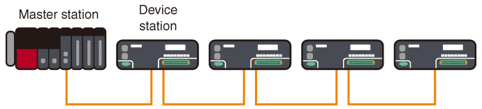
Network topology ideal for system configurations with high-speed/high-performance control
- High-speed communication is possible as the system is configured with CC-Link IE TSN-compatible device stations only
- Easier system configuration without an Ethernet switch
- Ideal for highly accurate motion control systems
Star topology
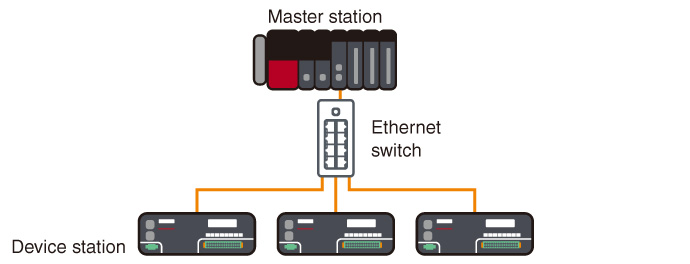
Network topology ideal for flexible system configurations
- Easily realizes distributed arrangement of device stations with an Ethernet switch
- Easy to change/rearrange equipment or system configuration
- Ideal for general production line control systems
Ring topology
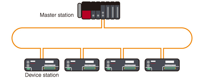
Network topology ideal for systems requiring high reliability *19
- Maintain data communications with normal stations even if a cable is disconnected or an error occurs in one of the device stations
- Configuration without requiring an Ethernet switch
- Ideal for continuously operating control system
- *19.Mixing with star topology or line topology is not supported.
CC-Link IE TSN Class
CC-Link IE TSN certifies nodes and switches to a specific class level according to its functionality and performance classification. Products can be classified as either class A or B. For the CC-Link IE TSN Class of each product, please check the CC-Link Partner Association website or the relevant product catalog or manual. Supported functions and system configuration may differ according to the CC-Link IE TSN Class of products used. For example, products compatible with class B are necessary to configure a high-speed motion control system. For details of configuring systems with both class A and class B devices, please refer to relevant master product manual.
System configuration
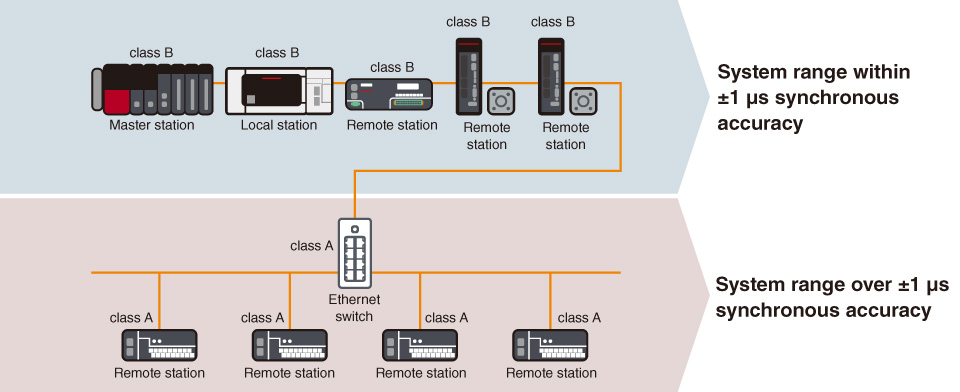
- Synchronous accuracy of a system varies relative to the combination of connected devices and switches CC-Link IE TSN Class
- Use class B Ethernet switch when configuring a star topology with class B devices
- Use class B devices when configuring a system within ±1 µs high-accuracy synchronization, connect class A devices to a separate branch line from class B devices (for details of system configuration, please refer to relevant master product manual)
- Mitsubishi Electric's block type remote modules comply both class B and A