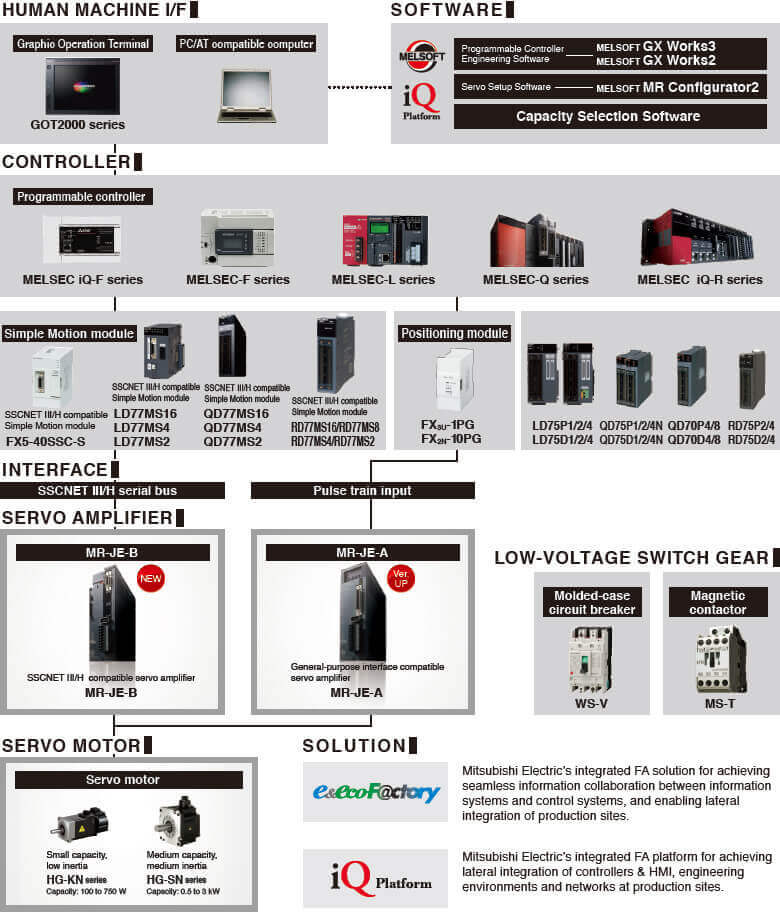
Servo
MELSERVO-J4 SERIES
A Complete system lineup to meet your production and manufacturing needs
Responding to expanding applications such as semiconductor and LCD manufacturing, machine tools, robots, and food processing machines, MELSERVO-J4 is flexibly coordinated with Mitsubishi Electric's other product lines such as Motion controllers, networks as well as displays and programmable controllers. MELSERVO-J4 allows you to freely create an advanced servo system.
Industry-leading Basic Performance
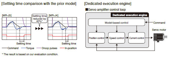
Industry-leading Level of Servo Amplifier Basic Performance
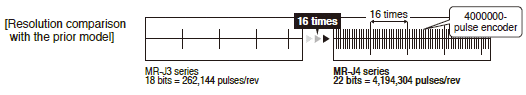
Speed frequency response of 2.5 kHz is achieved by applying our original high-speed servo control architecture evolved from the conventional two-degrees-of-freedom model adaptive control to the dedicated execution engine. Together with a high-resolution absolute position encoder of 4,194,304 pulses/rev, fast and accurate operation is enabled. The performance of the high-end machines is utilized to the fullest.
Improving Machine Performance with High-performance Servo Motors
Rotary servo motors achieve high-accuracy positioning and smooth rotation with a high-resolution encoder and improved processing speed.
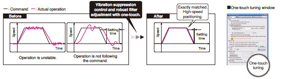
Advanced Servo Gain Adjustment Function
One-touch Tuning
Just turn on the one-touch tuning function to complete servo gain adjustment automatically, including machine resonance filter, advanced vibration suppression control II*1, and robust filter for maximizing your machine performance. This function also sets responsibility automatically, while the real-time auto tuning requires manual setting. Moreover, a new method*2 allows to create an optimum tuning command inside the servo amplifier.
*1.The advanced vibration suppression control II automatically adjusts one frequency.
*2.This new method is available with MR-J4-B/MR-J4W_-B/MR-J4-A with software version of C1 or later.
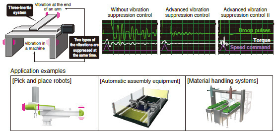
Advanced Vibration Suppression Control II
The advanced vibration suppression control II suppresses two types of low frequency vibrations owing to vibration suppression algorithm which supports three-inertia system. This function is effective in suppressing residual vibration with relatively low frequency of approximately 100 Hz or less generated at the end of an arm and in a machine, enabling a shorter settling time. Adjustment is easily performed on MR Configurator2.
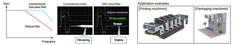
Robust Filter
Achieving both high responsibility and stability was difficult with the conventional control in high-inertia systems with belts and gears such as printing and packaging machines. Now, this function enables the high responsibility and the stability at the same time without adjustment. The robust filter gradually reduces the fluctuation of torque in a wide frequency range and achieves more stability as compared to the prior model.
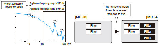
Expanded Machine Resonance Suppression Filter
With advanced filter structure, applicable frequency range is expanded from between 100 Hz and 4500 Hz to between 10 Hz and 4500 Hz. Additionally, the number of simultaneously applicable filters is increased from two to five, improving vibration suppression performance of a machine.
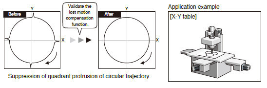
Lost Motion Compensation Function
This function suppresses quadrant protrusion caused by friction and torsion generated when the servo motor rotates in reverse direction. Therefore, the accuracy of circular path will be improved in trajectory control used in XY table, etc.
* This function is not available with MR-J4W2-B and MR-J4W3-B.
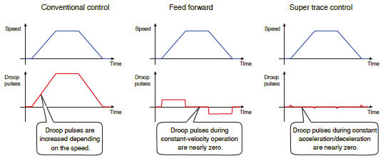
Super Trace Control
This function controls droop pulse to nearly zero not only during constant operation, but also during constant acceleration/deceleration. The trajectory accuracy will be improved in high rigidity machines.
* This function is not available with MR-J4W2-B and MR-J4W3-B.
A Variety of Functions for Various Applications
* Use a compatible controller.
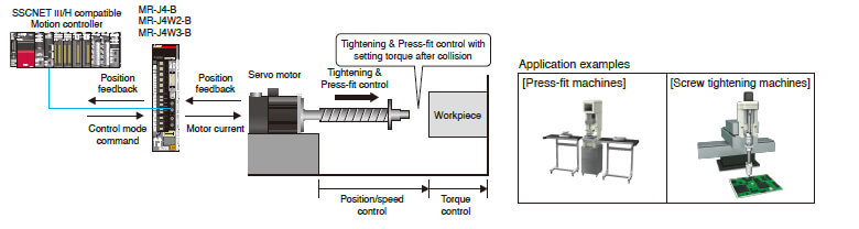
Tightening & Press-fit Control 
Position/speed control switches to torque control smoothly without stopping or changing the speed or the torque rapidly. Load to the machine is reduced, and high-quality molding is achieved for an application where control is switched from position to torque such as Tightening & Press-fit control or insertion of a work, and cap or screw tightening.
* Available with MR-J4-B/MR-J4W2-B/MR-J4W3-B.
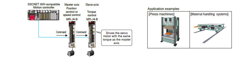
Master-slave Operation Function
With the master-slave operation function of MR-J4-B servo amplifier*, the torque of a master axis will be transmitted to slave axes through the driver communication. This enables a torque control operation with the slave axes, using the torque as a command. No additional wiring is required because the torque data is transmitted from the master axis to the slave axes via SSCNETIII/H.
* This function is available with MR-J4-B servo amplifier with software version A8 or later.
Scale Measurement Function 
The scale measurement function of MR-J4-GF/MR-J4-B*1/MR-J4W2-B*1 servo amplifiers*2 enables to transmit position information of a scale measurement encoder to the controller when the scale measurement encoder is connected in semi closed loop control.
The data of linear or synchronous encoders are transmitted to the servo system controller via the servo amplifier, achieving less wiring.
*1. This function is available with the servo amplifier with software version A8 or later, but not available with MR-J4W2-0303B6.
*2. Use corresponding servo amplifier (MR-J4-GF/MR-J4-GF-RJ/MR-J4-B/MR-J4-B-RJ) for load-side encoder.
Applicable for Various Control and Driving Systems
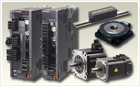
Compatible Servo Motors
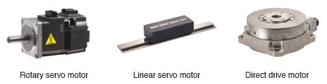
MR-J4 series servo amplifier operates rotary servo motors, linear servo motors, and direct drive motors as standard*.
* Not all of the servo amplifiers are compatible with all three of these servo motors. For the combination, refer to "Product lines" in the catalog.
1-axis/2-axis/3-axis Servo Amplifiers
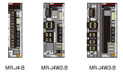
For SSCNETIII/H compatible servo amplifiers, 2-axis and 3-axis types are available in addition to 1-axis type, enabling flexible systems based on the number of control axes.
Compatible with Fully Closed Loop Control
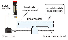
MRJ4-GF/MR-J4-B/MR-J4-A servo amplifier is compatible with fully closed loop control system*1. Accurate control of load-side position is achieved*2.
*1. MR-J4-GF/MR-J4-B/MR-J4-A servo amplifier is compatible with two-wire type serial linear encoders. For four-wire type serial and pulse train interface (A/B/Z-phase differential output type) linear encoders, use MR-J4-GF-RJ/MR-J4-B-RJ/MR-J4-A-RJ.
*2. Some models are not compatible with the fully closed loop control system. Refer to "Product lines" in the catalog.
Wide Range of Power Supplies and Capacities
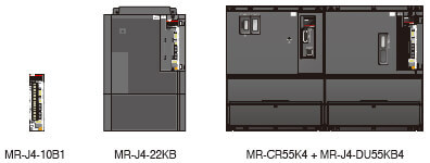
MR-J4-B/MR-J4-A servo amplifiers support 3-phase 200 V AC/400 V AC, 1-phase 100 V AC, and 48 V DC/24 V DC for the main circuit power supply, and the capacity ranges from 30 W* to 55 kW.
For MR-J4-GF, 3-phase 200 V AC/400 V AC is supported. In addition, MR-J4-GF-RJ/MR-J4-B-RJ/MR-J4-A-RJ supports DC power input.
* Servo amplifiers of 30 W is compatible with a power supply of 48 V DC/24 V DC.
For MR-J4-GF, 3-phase 200 V AC/400 V AC is supported. In addition, MR-J4-GF-RJ/MR-J4-B-RJ/MR-J4-A-RJ supports DC power input.
Maximum Command Pulse Frequency
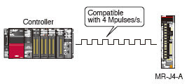
General-purpose interface compatible MR-J4-A servo amplifier supports maximum command pulse frequency of 4 Mpulses/s (when differential receiver is used).
When open collector is used, both sink and source inputs are enabled.
When open collector is used, both sink and source inputs are enabled.
Built-in Positioning Function for Simple System
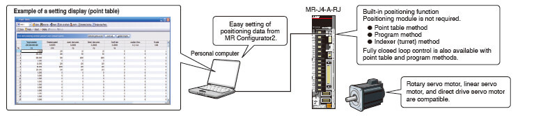
Servo Amplifier with Built-in Positioning Function
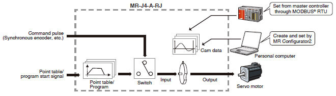
MR-J4-A-RJ*1 has a built-in positioning function, enabling positioning operation with point table, program-based, and indexer (turret) methods.
With this servo amplifier, a positioning system is configured without a Positioning module (command pulse). Positioning command is executed by input/output signals or RS-422/RS-485 communication (up to 32 axes). MR Configurator2*2 allows easy setting of the positioning data.
*1. Use MR-J4-A-RJ servo amplifiers with software version B3 or later when using the positioning function.
*2. Use MR Configurator2 with software version 1.25B or later. Be sure to update your MR Configurator2 to the latest version.

Setting position data (target position), servo motor speed, and acceleration/deceleration time constants in point table is as easy as setting a parameter. Up to 255 points are settable for the point table. The positioning operation is performed with a start signal after selecting the point table No.

* Point table can be set with push buttons on the servo amplifier or MR-PRU03 parameter unit along with MR Configurator2.

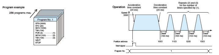
Create positioning programs with dedicated commands. The positioning operation is performed with a start signal after selecting the program No. The program-based method enables more complex positioning operation than the point table method. Maximum of 256 programs are settable. (The total number of steps of program: 640)
* MR Configurator2 is required to create programs.

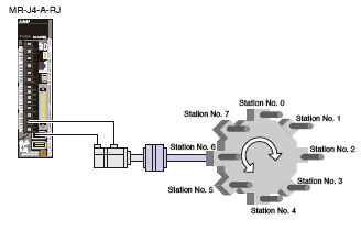
Perform positioning operation by specifying equally divided stations (up to 255 stations). The travel distance will be calculated automatically based on the number of equally divided stations set in the parameter. The positioning operation is performed with a start signal after selecting the station position No.
In addition to rotation direction specifying indexer and shortest rotating indexer, backlash compensation and override function are also available.
With this servo amplifier, a positioning system is configured without a Positioning module (command pulse). Positioning command is executed by input/output signals or RS-422/RS-485 communication (up to 32 axes). MR Configurator2*2 allows easy setting of the positioning data.
In addition to rotation direction specifying indexer and shortest rotating indexer, backlash compensation and override function are also available.
* Fully closed loop control mode and linear servo motor control mode are not supported by the indexer (turret) method.
New Useful Functions with Positioning Function
New useful functions are added to the positioning function: simple cam function, encoder following function, command pulse input through function, mark sensor input compensation function, and communication functions (MODBUS® RTU, Point to Point positioning, and current position latch function). Apply these useful functions to a wide variety of applications to configure positioning system easily. Use MR-J4-A-RJ servo amplifier with software version B7 or later. These functions are not available with MR-J4-03A6-RJ.

MR Configurator2 enables to create various patterns of cam data. Command pulse or point table/program start signal is used as input to the simple cam. The input command will be outputted to the servo motor according to the cam data.

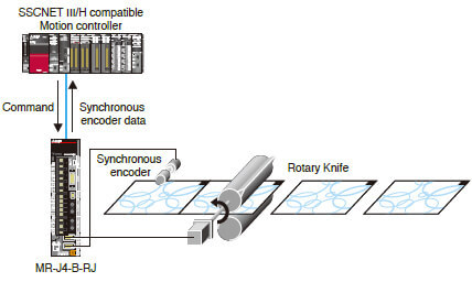
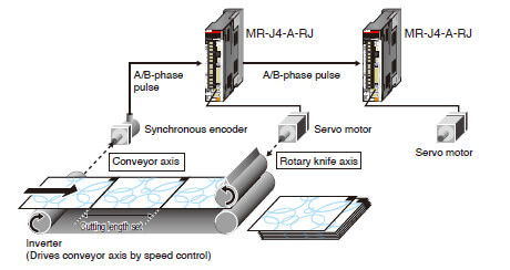
With the encoder following function, the servo amplifier receives A/B-phase output signal from the synchronous encoder as command pulse, and the input command will be outputted to the servo motor according to the cam data. Setting cam data that matches with the sheet length, a diameter of the rotary knife axis, and the synchronous section of the sheet enables a system in which the conveyor axis and the rotary knife axis are synchronized. Up to 4 Mpulses/s of input from a synchronous encoder is compatible with the servo amplifier.
The command pulse input through function allows the first axis to output A/B-phase pulses which are received from the synchronous encoder to the next axis, enabling a system in which the second and later axes are synchronized with the synchronous encoder.


In addition to RS-422/RS-485 communication (Mitsubishi general-purpose AC servo protocol), RS-485 communication (MODBUS® RTU protocol) is supported. MODBUS® RTU protocol is compatible with function code 03h (Read holding registers), etc.
Controlling and monitoring of the servo amplifier is possible by external devices.
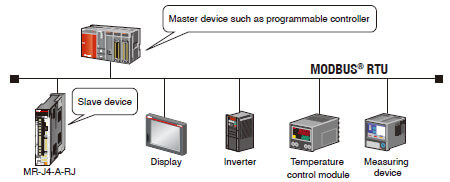
* RJ-45 junction connector terminal block and RJ-45 compatible cable designed for MR-J4-A-RJ are required.

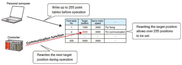
Up to 255 points of Point to Point positioning are enabled when the target position is set in the point table in advance. Rewriting the next target position during a operation is also possible by the communication function.

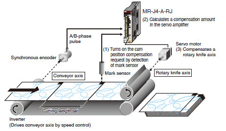
Based on the data latched by the mark detection function (current position latch*), a target position is compensated by being written in the point table.
* When the mark detection signal turns on, a current position will be latched, and the latched data will be read with the communication function.
Example: Executing positioning compensation when a product is dispositioned by 50 on a handling pallet.
Start an operation by specifying point table No. 1 (target position: 1000).
Communication function (current latch) measures a position gap with the mark detection function and writes the position gap of 50 to the target position in point table No. 2 for compensation during the operation.
After the operation of point table No. 1 is completed with a position gap of 50, start the operation by specifying point table No. 2. The product will be set to the right position.

All-rounder Network with CC-Link IE Field
All-in-One Network 
The network is designed to simultaneously handle distributed control, I/O control, and motion control. CC-Link IE Field Network lets you connect field devices such as programmable controllers, I/O modules, high-speed counter modules, servo amplifiers, inverters, and displays, providing optimal network which best fits the needs of the application.
Choose from star, line, or ring* topology suitable for layout of lines and machines.
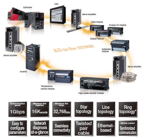
* The Simple Motion modules are not compatible with ring topology.
Servo Amplifier
มีรุ่นที่ทำงานร่วมกับ SSCNETIII/H, รุ่นสำหรับมอเตอร์ 2-3 แกน, รุ่นสำหรับงานทั่วไป (อินพุทพัลส์และอะนาล็อก) สอดคล้องกับมาตรฐานความปลอดภัย
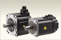
มอเตอร์เซอร์โว
Encoder ความละเอียดสูง 4 ล้านพัลส์/รอบ, ใช้กับไฟ 200/400VAC และช่วงผลิตภัณฑ์ตั้งแต่50W จนถึง 22kW
ซีรีส์ HG-KR/HG-MR/HG-SR/HG-JR/HG-RR/HG-UR
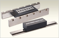
Linear Servo Motor
เป็นมอเตอร์เซอร์โวเคลื่อนที่แนวราบ มี 4 ซีรีส์ (LM-H3/LM-U2/LM-F/LM-K2) สำหรับการใช้งานที่หลากหลาย
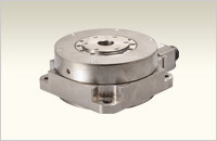
Direct Drive Motor
การจับคู่ที่ดีที่สุดสำหรับการใช้งานที่ต้องการความเร็วต่ำและแรงบิดสูง มีให้เลือก 4 โครงสร้างที่แตกต่างกันในมอเตอร์ 12 รุ่น
Servo System