


Product Features
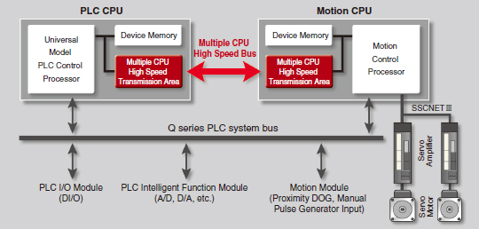
Multiple CPU Control by PLC CPU and Motion CPU
CPU loads are distributed by sharing tasks between the Motion controller and the Programmable controller. Complex servo controls are executed by the Motion controllers, while machine and information control is managed by the Programmable controllers. By selecting the Motion CPU and PLC CPU according to the application, a flexible system is configured. The program of Motion CPU is described with the Motion SFC program.
[Multiple CPU High Speed Bus]
- Equipped with a Multiple CPU high speed bus reserved specifically for CPUto-CPU communication.
With this reserved Multiple CPU high speed bus, data transfer of 0.88ms period is possible for up to 14k words. - The Multiple CPU high speed transmission cycle is synchronized with the motion control cycle thus optimizing the control system.
■Introducing easy-to-use Motion dedicated PLC instructions.
[PLC program interrupt for Multiple CPUs synchronization]
■Using the new PLC interrupt function synchronized with the motion operation cycle (0.88ms),
it is possible to achieve real time processing of the ladder program.
High Response Control
The Motion operation cycle of 0.22 ms/4 axes is achieved to meet customer needs for a shorter tact time. Even at an operation cycle of 0.44 ms, up to 10 axes are controlled without losing high response.
[Perfect for smooth curve control]
The command data from the Motion controller is transmitted to the servo amplifier every 0.22 ms. Motion Controller with Servo amplifier
(MR-J4-B) and servo motor (HG-KR motor: 4,194,304pulse/rev) achieves the shorter operation cycle and smooth motion.
Control Flow
Reduced Wiring, Space Saving
The number of wires and parts is drastically reduced when the Motion controller is used with 2-axis servo amplifier or 3-axis servo amplifier of MR-J4 series. When the Motion controller is used with MR-J4W3-B servo amplifier (3-axis type), the installation space is reduced by approximately 30%.
High-speed Synchronous Network SSCNETIII/H
Advanced Synchronous Control
The advanced synchronous control can be achieved using software instead of controlling mechanically with physical gears, shafts, clutches, speed change gears or cams etc. Additionally, a cam is easily created with the cam auto-generation function.The synchronous control can be started/ended on axis-by-axis basis.Axes in synchronous and positioning controls can be used together in one program. Speed-torque control can be performed simultaneously with the synchronous control.
[Control flow]
[Synchronous control parameters]
●The synchronous control is easily executed just by setting parameters.
●The movement amount of the main shaft can be transmitted to output axes via the clutch.
● "Command generation axis" is not considered as a control axis; therefore the output axes can be set using all of the available control axes.
Safety Observation Function
The safety system is compliant with "EN ISO13849-1:2008 Category 3 PLd" and "EN62061 SIL CL2" (these standards are harmonized with European Machine Directives). Functional safety (STO, SS1, SS2, SOS, SSM, SBC, SLS) according to IEC61800-5-2 are available as standard, as well as the safety signal comparison function, which confirms the status of the input/output signals by the Motion CPU and the PLC CPU. The operating conditions for these functions are freely programmed by using the PLC CPU and Motion CPU ladder circuits.
Speed monitoring function
The motor speed is monitored not to exceed the "Safety Speed" by the Motion CPU and the PLC CPU.
Safety signal comparison function
The safety input signals are monitored using the Motion CPU, PLC CPU and safety signal module.
Engineering Environment MELSOFT MT Works2
A robust and easy-to-use programming environment for advanced Motion control.
[System Design]
- You can easily set servo amplifiers and various modules with a graphical system setting screen.
- The complicated electric gear settings can be completed just by specifying the mechanical configuration (reduction ratio, ball screw pitch, etc.).
[Programming]
- User-friendly functions for program development.
- Easily divert the existing SFC program from the original project to the new project just by drag&drop.
[Setup and Adjustment]
- Simulator function executes the debugging of the Motion SFC program and the advanced synchronous control on desktop without using an actual machine.
- Operation check and troubleshooting are powerfully supported with data collection and wave displays which are synchronized to the Motion operation cycle.
Functions List
| Motion controller | ||
|---|---|---|
| Q173DSCPU | Q172DSCPU | |
| Servo amplifier interface | SSCNETIII/H | |
| 2 lines | 1 line | |
| Connectable servo amplifier | MR-J4-B | |
| Number of control axes | Up to 32 axes | Up to 16 axes |
| Operation cycle[ms] | From 0.22ms | |
| Engineering Environment | MELSOFT MT Works2, MR Configurator2 (Note-1) | |
| Programming method | Motion SFC | |
| Control modes | Position control, Speed control, Torque control, Tightening & press-fit control, Synchronous control, Cam control, Advanced synchronous control | |
| Positioning control | PLinear interpolationm, Circular interpolation, Continuous trajectory control, Helical interpolation, Position follow-up control, Speed control with fixed position stop, High-speed oscillation control, Speed/position switching control | |
| Acceleration/deceleration process | Trapezoidal acceleration/deceleration, S-curve acceleration/deceleration, Advanced S-curve acceleration/deceleration | |
| Manual control | JOG operation, Manual pulse generator, JOG operation simultaneous start | |
| Acceleration/deceleration process | Current value change, Target position change, Torque limit value change, Speed change | |
| Home position return method | Proximity dog method 1, Proximity dog method 2, Scale home position signal detection method, Count method 1, Count method 2, Count method 3, Data set method 1, Data set method 2, Dog cradle method, Stopper method 1, Stopper method 2, Limit switch combined method, Dogless home position signal reference method | |
| Auxiliary functions | Forced stop method, Hardware stroke limit method, Software stroke limit method, Absolute position system, Amplifier-less operation method, Unlimited length feed method, Optional data monitor method, Mark detection method, ROM operation function, M-code output method, Error history, Digital oscilloscope method, Safety observation function, Vision system connection function, Software Security Key Function, High-speed reading function, Limit switch output method, Cam auto-generation method | |
(Note-1): MELSOFT MR Configurator2 is included in MELSOFT MT Works2.