


Product Features
Advanced features for world-class safety
Equipped with the Safety Sub-Function
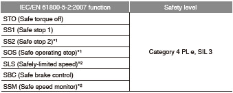
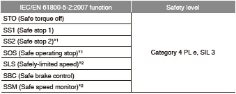
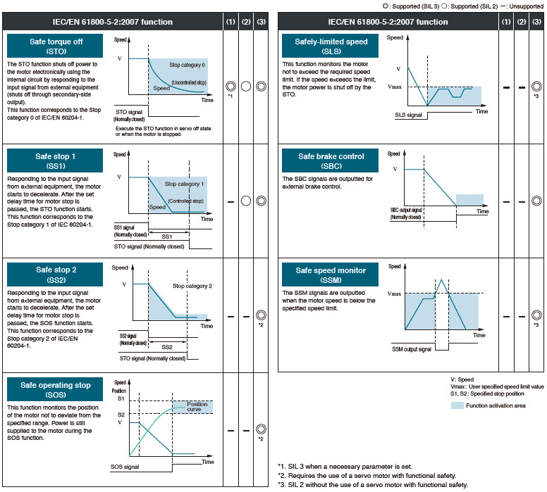
Functions Compliant with IEC/EN 61800-5-2
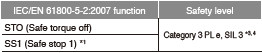
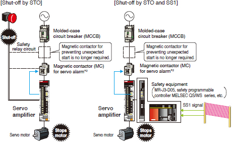
*1. Safety equipment (MR-J3-D05, safety programmable controller MELSEC QS/WS series, etc.) is required.
*2. For MR-J4 series servo amplifier, magnetic contactors are not required to meet the STO requirements. However, this illustration has a magnetic contactor installed to prevent servo alarms and electric shock.
*3. Servo amplifiers manufactured in Japan in June 2015 or later, or in China in December 2015 or later are required, and a parameter needs to be set.
*4. For Category 3 PL e, SIL 3, use compatible safety equipment and set the parameters. When MR-J3-D05 is used, safety level is Category 3 PL d, SIL 2.
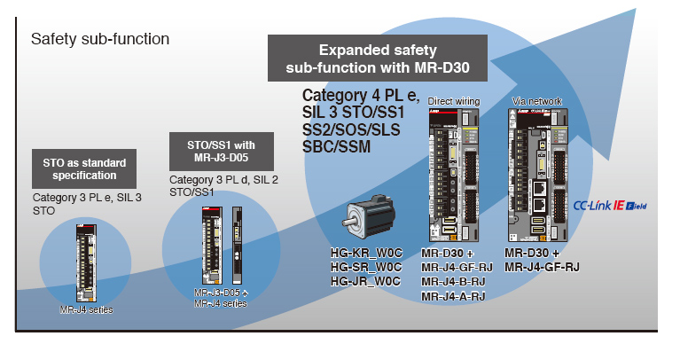
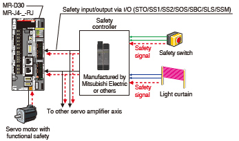
Increasing Safety Level with MR-D30 Functional Safety Unit
Achieving Category 4 PL e, SIL 3
● By wiring to MR-D30 functional safety unit
Safety level is Category 4 PL e, SIL 3 when the safety signals are inputted directly to MR-D30 functional safety unit. The safety sub-function is operated on the MR-D30 by parameter setting, and therefore expansion of the safety sub-function is possible independent of controllers.
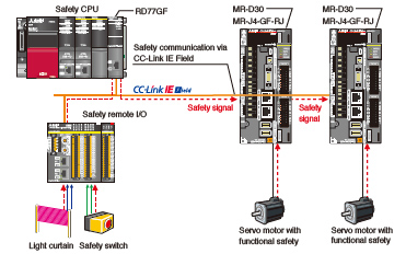
● By CC-Link IE Field Network
When MR-J4-GF-RJ is combined with R_SFCPU-SET safety CPU and RD77GF Simple Motion module, MR-J4-GF-RJ receives the safety signal data though CC-Link IE Field Network connected to RD77GF, and thus wiring the safety signals to the I/O of MR-D30 is not necessary.
Achieving IEC/EN 61800-5-2 Functions
(1) Functions achievable with MR-J4-GF(-RJ)/MR-J4-B(-RJ)/MR-J4W_-B/MR-J4-A(-RJ)
(2) Functions achievable with MR-J3-D05 and MR-J4-GF(-RJ)/MR-J4-B(-RJ)/MR-J4W_-B/MR-J4-A(-RJ)
(3) Functions achievable with MR-D30 + MR-J4-GF-RJ/MR-J4-B-RJ/MR-J4-A-RJ
Maintenance Function to Achieve TCO* Reduction*TCO : Total Cost of Ownership
Compliance with SEMI-F47
MELSERVO-J4 series servo amplifier complies with SEMI-F47 standard* corresponding to semiconductors and FPD manufacturing systems. (SEMI-F47 is not applicable to 1-phase 100 V AC, 1-phase 200 V AC, and DC input. To comply with SEMI-F47 with 9 kW or larger servo amplifiers, the dynamic brake is not usable.)
* The control power supply of the servo amplifier complies with SEMI-F47. Note that the backup capacitor may be required depending on the power impedance and operating situation for the instantaneous power failure of the main circuit power supply. Be sure to perform a test on your machine to meet the SEMI-F47 Voltage Sag Immunity Standard. Please use the 3-phase power supply for the servo amplifier input.
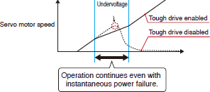
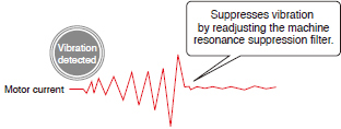
Tough Drive Function
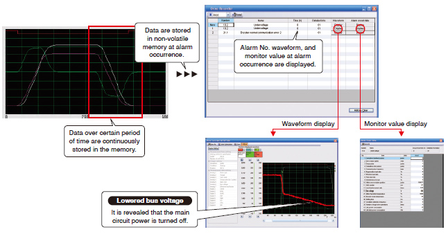
Large Capacity Drive Recorder
● Servo data such as motor current and position command before and after the alarm occurrence are stored in non-volatile memory of the servo amplifier. Reading the servo data on MR Configurator2 helps you analyze the cause of the alarm.
● Check the waveform ((analog 16 bits × 7 channels + digital 8 channels) × 256 points) and the monitor values of the past 16-time alarms in the alarm history.
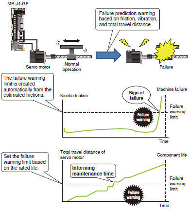
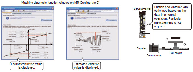
Machine Diagnosis Function
This function detects changes in mechanical parts (ball screw, guide, bearing, belt, etc.) by analyzing changes in machine friction, load moment of inertia, unbalanced torque, and vibration components from the data inside a servo amplifier, supporting timely maintenance of these parts.
![[Example of an alarm window on MR Configurator2]](http://www.mitsubishifa.co.th/files/upload/img_210823_1010171004632169.jpg)
![[Three-digit alarm display]](http://www.mitsubishifa.co.th/files/upload/img_210823_100928452128881.jpg)