


Product
Product Features
Servo Amplifier Model Designation
Model Designation for 1-Axis Servo Amplifier (Note 14)
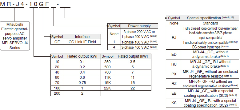
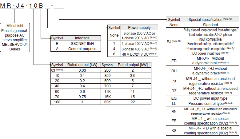
- Notes:
- Dynamic brake which is built in 7 kW or smaller servo amplifiers is removed. When the servo amplifiers without the dynamic brake are used, the servo motors coast to a stop and do not stop immediately at alarm occurrence or power failure. Take measures to ensure safety on the entire system. Refer to relevant Servo Amplifier Instruction Manual for details.
- A power supply of 1-phase 200 V AC is supported by 0.1 kW to 2 kW servo amplifiers.
- A power supply of 3-phase 400 V AC is supported by 0.6 kW and 1 kW or larger servo amplifiers.
- Available in 11 kW to 22 kW servo amplifiers. A regenerative resistor (standard accessory) is not enclosed. Refer to relevant Servo Amplifier Instruction Manual for details.
- A power supply of 1-phase 100 V AC is supported by 0.1 kW to 0.4 kW servo amplifiers.
- MR-J4-_B_-LL is available. Refer to "MR-J4-_B_-LL MR-J4-DU_B_-LL Servo Amplifier Instruction Manual" for the pressure control compatible servo amplifiers.
- The special coating (JIS C60721-3-3/IEC 60721-3-3 classification 3C2) is applied to the circuit board of the servo amplifier. Refer to relevant Servo Amplifier Instruction Manual for details.
- Positioning mode is supported by MR-J4-GF(-RJ)/MR-J4-A-RJ servo amplifiers.
- Supported by MR-J4-03A6(-RJ) servo amplifier.
- Only positioning mode is supported by MR-J4-03A6-RJ. The fully closed loop control, load-side encoder A/B/Z-phase input, and the functional safety unit are not supported.
- Only 200 V is available.
- For the servo amplifier software version which supports each function, refer to the specification page of each unit.
- When the servo amplifier is connected to CC-Link IE Field Network Basic, an MR-D30 functional safety unit is not supported.
- This section describes what each symbol in a model name indicates. Some combinations of symbols are not available.
Model Designation for Multi-Axis Servo Amplifier (Note 8)
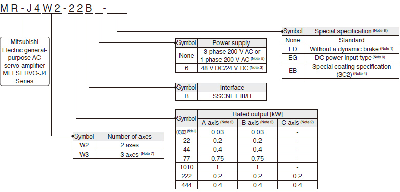
- Notes:
- Dynamic brake which is built in servo amplifiers is removed. When the servo amplifiers without the dynamic brake are used, the servo motors coast to a stop and do not stop immediately at alarm occurrence or power failure. Take measures to ensure safety on the entire system. Refer to relevant Servo Amplifier Instruction Manual for details.
- A-axis, B-axis, and C-axis indicate names of axes of the multi-axis servo amplifier. The C-axis is available for the 3-axis servo amplifier.
- Supported by MR-J4W2-0303B6 servo amplifier.
- The special coating (JIS C60721-3-3/IEC 60721-3-3 classification 3C2) is applied to the circuit board of the servo amplifier and the drive unit of 30 kW or larger. Refer to relevant Servo Amplifier Instruction Manual for details.
- A power supply of 1-phase 200 V AC is supported by 0.2 kW to 0.75 kW servo amplifiers.
- For the servo amplifier/drive unit software version which supports each function, refer to the specification page of each unit.
- Available only with 0.2 kW and 0.4 kW.
- This section describes what each symbol in a model name indicates. Some combinations of symbols are not available.
- Contact your local sales office for more details.
Unit Model Designation
Model Designation for Drive Unit
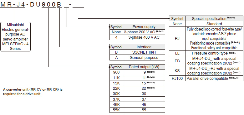
- Notes:
- The special coating (JIS C60721-3-3/IEC 60721-3-3 classification 3C2) is applied to the circuit board of the servo amplifier and the drive unit of 30 kW or larger. Refer to relevant Servo Amplifier Instruction Manual for details.
- A power supply of 3-phase 200 V AC is supported by 37 kW or smaller drive units.
- Available only with MR-J4-DU_B_(-RJ).
- Positioning mode is supported by MR-J4-DU_A_-RJ drive unit.
- MR-J4-DU_B_-LL is available in 30 kW or larger drive units. Refer to "MR-J4-_B_-LL MR-J4-DU_B_-LL Servo Amplifier Instruction Manual" for the pressure control compatible servo amplifiers.
- For the servo amplifier/drive unit software version which supports each function, refer to the specification page of each unit.
- Available only with the drive unit of 3-phase 400 V AC and 45 kW or higher.
- Refer to "Compatible Controllers" for compatible controllers.
Model Designation for Power Regeneration Converter Unit (Note 1, 3)

- Notes:
- The power regeneration converter unit is supported by MR-J4-DU_B(4)(-RJ) and MR-J4-DU_B4-RJ100 drive units. It is not supported by MR-J4-DU_A(4)(-RJ) drive unit. Refer to "MR-CV_ MR-CR55K_ MR-J4-DU_B_(-RJ) MR-J4-DU_A_(-RJ) Instruction Manual" for the combination with MR-J4-_B(4)(-RJ) servo amplifiers.
- Available only with the power regeneration converter unit of 400 V.
- This section describes what each symbol in a model name indicates. Some combinations of symbols are not available.
Model Designation for Resistance Regeneration Converter Unit (Note 1, 3)
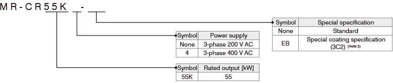
- Notes:
- One unit of resistance regeneration converter unit is required for each drive unit.
- The special coating (JIS C60721-3-3/IEC 60721-3-3 classification 3C2) is applied to the circuit board of the resistance regeneration converter unit. Refer to "MR-CV_ MR-CR55K_ MR-J4-DU_B_(-RJ) MR-J4-DU_A_(-RJ) Instruction Manual" for details.
- Use the resistance regeneration converter unit with MR-J4-DU_B(4)(-RJ) or MR-J4-DU_A(4)(-RJ) unit. The resistance regeneration converter unit is not compatible with MR-J4-DU_B4-RJ100 and 22 kW or smaller MR-J4-DU_B(4)(-RJ).