


Product
Product Features
Safety Programmable Controller
Safety programmable controller MELSEC-QS Series
The safety programmable controller is compliant with international safety standards, EN ISO 13849-1 Category 4/PL e and IEC 61508 SIL 3. It is ideal for medium to large-scale safety control systems. Ladder programs and certified safety function blocks*1 realize flexible programming.
*1. They can be used to structure EN ISO 13849-1 Category 4/PL e and IEC 61508 SIL 3 safety applications.
MELSEC-QS Series system configuration
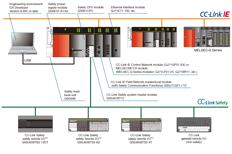
*2. Number of input points: 8 points (double wiring), No. of output points: 4 points (source + sink type)
*3. Number of input points: 8 points (double wiring)
*4. Number of output points: 4 points (source + sink type)
*3. Number of input points: 8 points (double wiring)
*4. Number of output points: 4 points (source + sink type)
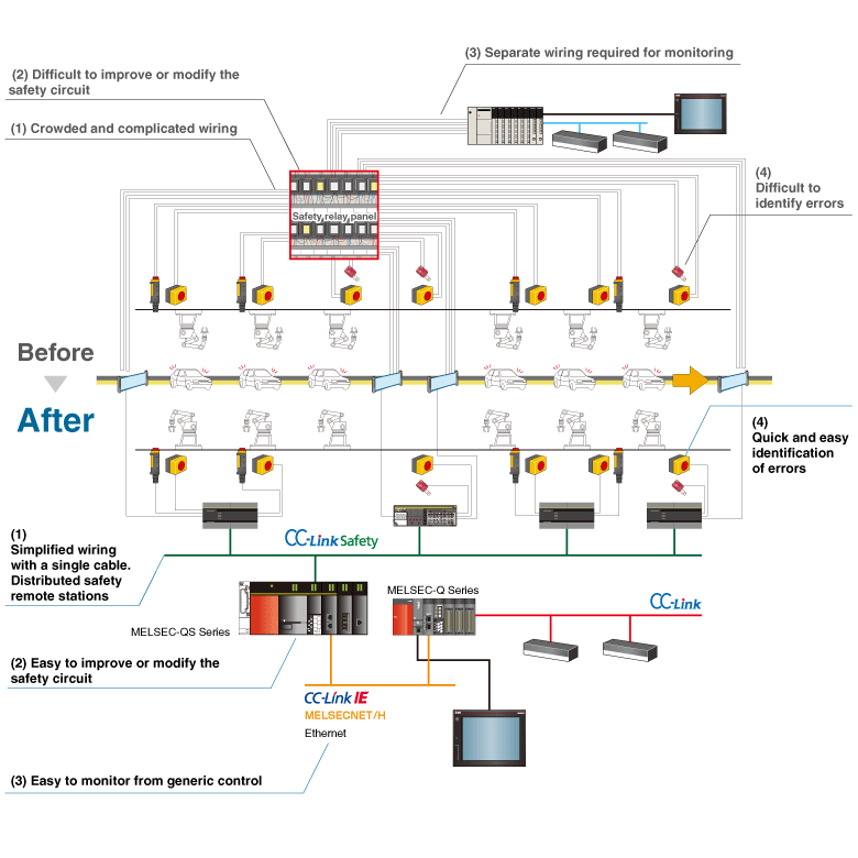
Reducing costs while increasing diagnostic capabilities and system flexibility
The MELSEC-QS Series solves the complicated wiring and time-consuming troubleshooting issues associated with previous safety relay systems.
Programming with ladder diagrams and safety FBs
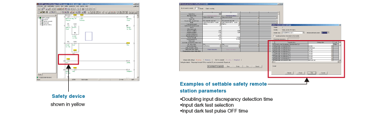
■ GX Developer
- Use GX Developer to start up MELSEC-QS Series safety control systems (programming, monitoring, diagnosis, and debugging). GX Developer can configure CC-Link Safety, CC-Link IE Field Network and safety remote station parameters.*5
*5. GX Works2 is necessary to configure CC-Link IE Field Network settings when using generic programmable controllers.
■ Safety FB (Function Block)*6
Functions that are frequently used for creating safety programs are provided as safety FBs. The safety FBs have been certified.
Safety FB list
| FB name | Function | Description |
|---|---|---|
| F+2HAND2 | Two hand switch Type II | Provides the two-hand control functionality. |
| F+2HAND3 | Two hand switch Type III | Provides the two-hand control functionality. (Fixed specified time difference is 500 ms.) |
| F+EDM | External device monitor | Controls a safety output and monitors controlled actuators, e.g. subsequent contractors. |
| F+ENBLSW | Enable switch | Evaluates the signals of an enable switch with three positions. |
| F+ESPE | Light Curtain (ESPE) | Safety-related FB for monitoring electro-sensitive protective equipment (ESPE). |
| F+ESTOP | Emergency Stop | Safety-related FB for monitoring an emergency stop switch. This FB can be used for emergency switch off functionality (stop category 0). |
| F+GLOCK | Guard Lock and Interlocking | Controls an entrance to a hazardous area via an interlocking guard with guard locking ("four state interlocking"). |
| F+GMON | Guard Monitoring | Monitors the relevant safety guard. There are two independent input parameters for two switches at the safety guard coupled with a time difference (Monitoring Time) for closing the guard. |
| F+MODSEL | Mode Selector | Selects the system operation mode, such as manual, automatic, and semi-automatic, etc. |
| F+MUTE2 | Muting with 2 sensors | Muting is the intended suppression of the safety function. (e.g., light barriers) In this FB, parallel muting with two muting sensors is specified. |
| F+MUTEP | Parallel muting | Parallel muting with four muting sensors is specified. |
| F+MUTES | Sequential muting | Sequential muting with four muting sensors is specified. |
| F+OUTC | Output control | Control of a safety output with a signal from the functional application and a safety signal with optional startup inhibits. |
| F+TSSEN | Testable safety sensor | Detects, for example, the loss of the sensing unit detection capability, the response time exceeding that specified, and static ON signal in signal-channel sensors systems. It can be used for external testable safety sensors. |
| F+EQUI | Dual input (NC + NC or NO + NO) | Converts two equivalent bit inputs (both NO or NC) to one bit with discrepancy time monitoring. This FB output shows the result of the evaluation of both channels. |
| F+ANTI | Dual input (NO + NC) | Converts two antivalent*7 bit inputs (NO/NC pair) to one bit output with discrepancy time monitoring. This FB output shows the result of the evaluation of both channels. |
*6. The safety FBs are provided for GX Developer version 8.82L or later. (QS001CPU is supported with the first five digits of serial number "11042" or later.)
*7. "Antivalent" means that during normal operation, the two inputs are in opposite states at the same time. This is sometimes called "complementary" or "non-equivalent".
*7. "Antivalent" means that during normal operation, the two inputs are in opposite states at the same time. This is sometimes called "complementary" or "non-equivalent".
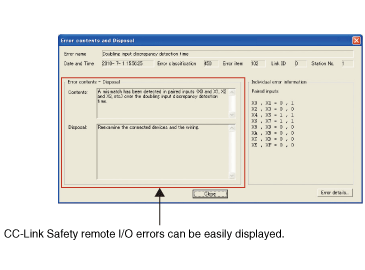
Easy error/failure troubleshooting
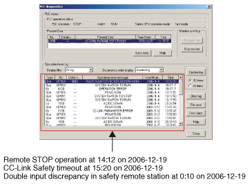
Debug functions
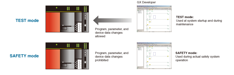
Debug functions (device test, write during RUN, etc.) are available in test mode.
Lineup
| Product name | Model * |
|---|---|
| Safety CPU | QS001CPU (-K) |
| Safety main base | QS034B (-K) |
| Safety power supply | QS061P-A1 (-K) |
| QS061P-A2 (-K) | |
| CC-Link IE Field Network master/local (with Safety Communication Functions) | QS0J71GF11-T2 |
| CC-Link Safety system master | QS0J61BT12 (-K) |
| CC-Link Safety system remote I/O | QS0J65BTB2-12DT (-K) |
| QS0J65BTS2-8D | |
| QS0J65BTS2-4T |
*: S-mark compatible part models are indicated in parentheses.