


Product Features

Improved safety


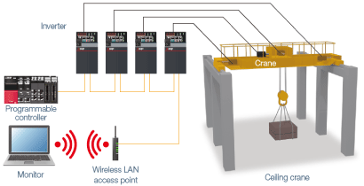
 Wireless access with hard-to-reach inverters
- Ethernet communication
Even if inverters are located in a high place, narrow area, or other hard-to-reach place, wireless access enables adjustments of inverter parameters, inverter monitoring (simultaneous monitoring of multiple axes possible), and inverter maintenance such as life diagnosis checks.
The FR-E800 inverter can be connected to FR Configurator2 using a commercially-available industrial wireless LAN*1 access point.*2
- *1:A wireless LAN suitable for the industrial use in severe environments or in environments requiring high reliability (redundancy).
- *2:Under certain environments or installation conditions, Ethernet communication through wireless LAN is not as stable as communication through wired LAN. Before starting operation, always check the communication status. Inverter operation (output shutoff, deceleration stop, etc.) when communication fails (due to reasons such as disconnection) can be selected by setting parameters. For applications requiring data transmission or update periodically or within a certain time period, a wired connection is recommended.
 Attaining both safety and productivity
- Functional safety
This will contribute to reduction in the initial safety certification cost.
Using the safety sub-functions compliant with IEC 61800-5-2 for the machinery or equipment will contribute to eliminate external devices or reduction in maintenance time, and ensure operators' safety. (Several conditions must be met to use this function.)
This will significantly reduce time required for maintenance or tooling and eliminate external devices such as ones used for monitoring the speed.
Use FR Configurator2 to set parameters related to the safety monitoring functions.
| Safety level (ISO 13849-1, IEC 61508) | SIL2, PLd, Cat.3 | SIL3, PLe, Cat.3 | SIL2, PLd, Cat.3 | |
|---|---|---|---|---|
| Safety sub-function (IEC 61800-5-2) | FR-E800、 FR-E800-E | FR-E800-SCE | FR-E700-SC | |
| STO | Safety torque off, coasting to stop | ● | ● | ● |
| SS1 | Safe stop 1, deceleration monitoring | ─ | ● | ─ |
| SLS | Safely-limited speed | ─ | ● | ─ |
| SBC | Safe brake control | ─ | ● | ─ |
| SSM | Safe speed monitor | ─ | ● | ─ |
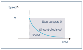
STO (safe torque off) function
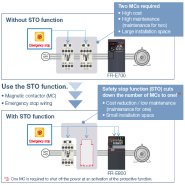
Driving power to the motor is electronically shut off by responding to the input signal from external equipment.
 SLS (safely-limited speed) function
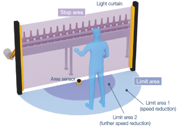
When an operator enters the limit area while a system is operating, operation of the system is not stopped and continues with a reduced speed.
The motor speed is calculated without using an encoder. This will contribute to wire and cost savings.
For details of operating conditions and risk assessment, refer to the Instruction Manual (Functional Safety).
(Functional Safety).